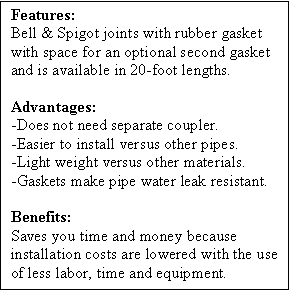
Bell & Spigot Couplers with “O” Ring Gasket
CPP BELL & SPIGOT with “O” Ring Gasket – these couplers come with a water seal restricting gasket manufactured per ASTM-F-477. These couplers meet the 13 psi Pre-Installation, Gravity Flow, Pipe Joint Laboratory Test ASTM-D-3212. State Highway Departments and others knowledgeable in pipe installing often note in writing pipe job installation specifications that Lab Tests of pipe joints are not intended to indicate any Field Performance of a pipe joint, but only a joint’s performance under ideal Lab conditions. For Installed Joint Testing, some inspecting authorites may call for ASTM-F-2487 (06), which is a specification written specifically for Polyethylene Corrugated Pipe Installed Joint performance.

CPP 12″-to-24″ meet the ASTM-D-3212 Lab Test 13.0 psi requirement with one ASTM-F-477 “O” Ring Gasket. CPP 30″-to-48″ with one “O” Ring Gasket, meet the ASTM-D-3212 13.0 psi level as modified with Factory Applied Stainless Steel Band around the Bell. The Stainless Steel Band may be Toggle Bolt tightened one or two turns after the pipe is assembled. This Toggle Bolt Field tightening sequence can assist in a Bell’s return to its pre-assembled normal circumference after being strained/stretched by an assembly that utilizes large equipment, which is prone to applying unknown insertion forces.
As with concrete, metal or clay pipes, the installer must take precautions at all coupling sites that have historically been a SINKHOLE formation problem of failure, no matter a pipe’s raw material base. Like any coupling junction, Man-Hole Tie-In, existing pipe Cross-over points, etc. extra installing care must be taken to insure that the uniform 95% Proctor Density compaction soil support is available per ASTM Installation specifications D-2321 and the PPI-CPPA Installation guide. The correct soil compaction level prevents deflection stresses on CPP Pipes from exceeding 5%, and thus protects from an over-deflection on the coupler’s “O” Ring Seals as well.
The bedding of the pipe and joints must be without Reverse Grades that could bend, pinch or misalign a joint assemblage that would prevent a joint seal. If CPP pipes are installed in soils that are expected to experience any movement from a future high water table or soil-moisture ratio change, a GRAVEL PACK LOADBEARING ENVELOPE ENCASED INSIDE A FILTER WRAP must be used. Soils not reinforced properly to withstand soil-moisture changes, can result in a MUSHY soil that will increase a pipe’s deflection to the point of jeopardizing a joint leak resistant gasket seal. This is particularly true in non-cohesive silts, Class IV, Class V and N/R soils. It should be noted that the flexibility of CPP pipes is an attribute that accommodates minor post installation soil settling and shifting, and thus prevents many opportunities of catastrophic differential, sheer loading related joint misalignments that are often experienced by the more rigid pipe system materials. The 20-foot sections of CPP pipes also reduce joint failure opportunities because there are fewer joints. However, in Class IV, V or other Fluctuating Water-Table prone soils, soils reinforcement practices (as noted in ASTM-D-2321) must be selected to assure performance as would be required for the installation of rigid pipe products. Under these site conditions, a CPP MASTIC WRAP COUPLER should be specified by the ENGINEER to avoid leakage that could lead to possible Sinkhole formations that may develop years after an installation.

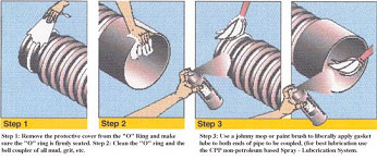
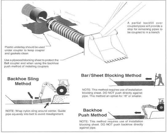
When using the CPP Bell and Spigot Gasket system, both the “O” Ring and the Bell Coupler must be lubricated with a Non-Petroleum, Bio-degradable pipe joint lubricant. First, the protective wrap should be removed from the gasket. The Male and Female Ends should be cleaned prior to lubrication to insure a secure gasket sealing opportunity. As corrugations can drag loose trench soil into the coupling joint area, a clean plastic sheet of construction film should be placed under the coupling joint work zone. The Bell End should cover two full pipe corrugations when fully seated.

Coverage Comparison Between Spray and Tub Lube
Spray – 16 oz can joints per can
Conventional Tub Lube
Joints per LB
4”
6”
8″
10″
12″
15″
18″
24″
30″
36″
42″
48″
75
50
37
30
25
20
16+
12+
10
8+
7+
6+
35
25
15
11
6
5+
3+
3
2-
2-
1+
1+
CPP, INC. recommends the use of Non-Petroleum base spray
Installation Comparison
Spray
Finger tip dispensing
Reduces labor 400%
No loss can system
Dissipates moisture on pipe
Does not freeze
NSF-61 approved
Tub Lube
Sloppy/messy Application
Labor Intensive
Loss due to spillage
Difficult wet pipe Application
Gels or freezes
Not all lubes potable

